






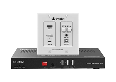
2 x 1 transmissor de trocadores de placas de parede sobre HDBT 3.0 Suporta trocadores automáticos e manuales (comandos de botão e API) entre as entradas de USB-C e HDMI “ USB-B. Entrada de USB-C completa suporta entrega de vídeo 4K e dados USB, bem como carga de 60W*. A entrada HDMI 2.0 suporta resoluções de vídeo até 4K@60Hz 4:4:4 8bit e HDCP 2.2. Suporta a transmissão de 4K@60Hz 4:4:4 sinal de 8bit até 40m/131ft e de 4K@30Hz 4:4:4 sinal de 8bit até 70m/230ft através de um Cat 6A…
USB in the Modern Meeting Room
Physical-Layer Engineering for Microsoft Teams Rooms and BYOM Spaces


23
Jul
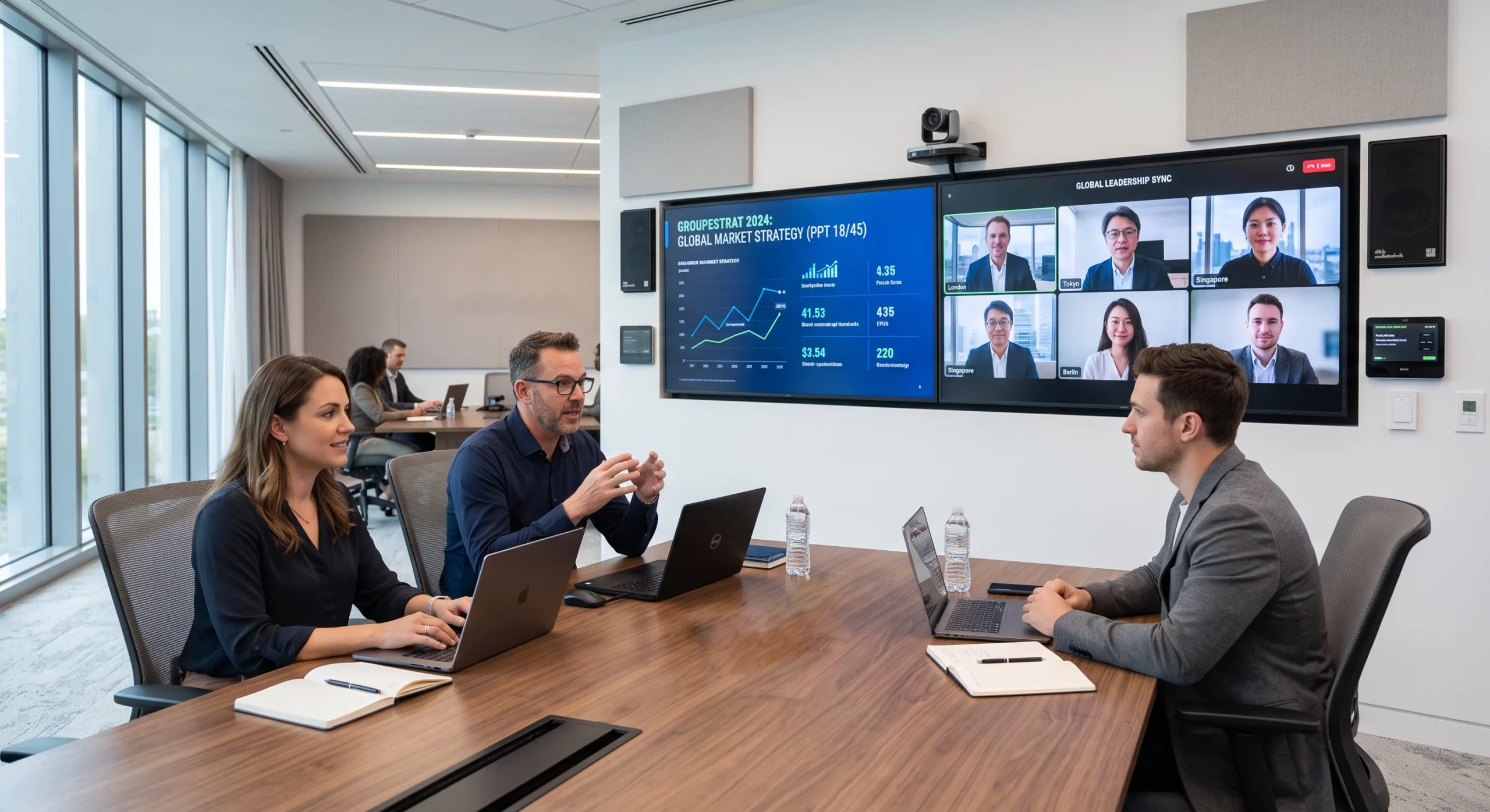
Conference-room instability is routinely misdiagnosed as a device or driver defect when the true origin is the USB transport underneath. This paper examines how signal integrity, bus topology, and power delivery each constrain USB in a meeting-room deployment, defines design rules for building rooms that hold up at fleet scale, and shows how the Infobit iTrans WP70HBC and iShare X400 Pro remove the most fragile links from the signal chain.
|
40 m |
60 W |
0 Cables |
|
4K60 + USB OVER ONE CAT 6A |
USB-C CHARGING AT THE TABLE |
WIRELESS BYOM CONFERENCING |
EXECUTIVE SUMMARY
In a Microsoft Teams Room or any modern UC space, USB has quietly become room infrastructure. A single bus now transports the camera stream, echo-cancelled audio in both directions, touch-panel control, and shared content. Yet most rooms are still cabled as if USB were a desktop accessory — and the result is a familiar pattern of intermittent faults that resist troubleshooting because they originate below the operating system, at OSI Layer 1.
Infobit’s position is straightforward: the USB transport in a meeting room should be designed with the same discipline applied to a structured network — with distance budgets, topology limits, and power margins calculated before installation, not discovered after the first failed call. Where a run exceeds what passive copper can honestly deliver, the signal should move onto an engineered transport such as HDBaseT 3.0, or leave the cable entirely through wireless BYOM.
OVERVIEW
When a room camera stutters or a conferencing DSP disappears from the host, the instinctive response is to replace the endpoint. In Infobit’s field experience the endpoint is rarely at fault: the same device that fails in the room passes every bench test, because the bench never reproduces the room’s cable lengths, hub chains, and power draw. The fault lives in the transport.
These transport faults are uniquely frustrating for IT teams because they are invisible to software tooling. Enumeration errors present as devices that were “never connected”; marginal signal integrity presents as occasional frame loss; supply-voltage sag presents as endpoints that reboot themselves mid-meeting. None of it is captured in application logs, so rooms earn a reputation for being “flaky” while every component in them tests clean.
The following section breaks the problem into its three physical constraints — signal, topology, and power — and a fourth, organizational constraint: how extension is chosen.
PHYSICAL-LAYER FAILURE ANALYSIS
Every unreliable USB room Infobit has audited traces back to at least one of four constraints. Three are laws of physics; the fourth is a procurement habit.
|
Constraint |
Physical Mechanism |
How It Presents in the Room |
|
Sinal |
Passive USB 3.x copper attenuates rapidly with length; beyond roughly the 2–3 m design envelope, the error rate rises steeply once the link is fully loaded. |
Camera frame drops and resolution fallback under real-call load, while a short bench connection tests perfectly. |
|
Topology |
The USB specification limits how many hub tiers a host will enumerate — and displays, video bars, and extenders each embed hubs the installer never sees. |
Peripherals intermittently vanish and reappear; devices enumerate in a different order after every reboot. |
|
Potência |
Resistance across long copper runs drags the 5 V bus below the 4.75 V floor the specification guarantees to endpoints. |
Cameras and audio devices power-cycle at random — indistinguishable from a driver fault, and absent from every log. |
|
Arquitetura |
Extension is often an after-the-fact purchase: optical cables solve EMI but tolerate little mechanical abuse, and category-cable extenders introduce timing delay of their own. |
The “fix” installed after the first failure becomes the next failure — crushed fiber in a floor box, or control latency users can feel. |
The common thread: each constraint produces symptoms one or two layers above where the cause lives, which is why software-first troubleshooting cycles through drivers, firmware, and replacement hardware without ever converging.
SOLUTION DESCRIPTION
Infobit’s design method treats the room’s USB plane as a small network with a calculated budget, then removes the weakest links from that network altogether.
Design rules
- Survey before you cable — document every USB endpoint in the room, including the hubs hidden inside displays and video bars, and count enumeration tiers from the host outward.
- Budget power like voltage matters — because it does. Sum endpoint draw per segment, and provide local or extender-delivered power wherever a run approaches the margin.
- Keep passive copper inside its envelope — no passive USB 3.x run should be asked to do at 5 m what it was specified to do at 2.
- Engineer the long runs — carry anything beyond the envelope over a purpose-built transport with its own power story, rather than a longer version of the same cable.
- Standardize the design — one validated room architecture, repeated across the fleet, turns troubleshooting from archaeology into pattern-matching.
iTrans WP70HBC — the long run, engineered
The iTrans WP70HBC applies HDBaseT 3.0 to the table-to-display problem: a 2-gang wall or table plate that carries uncompressed 4K@60Hz 4:4:4 video, USB 2.0 data at up to 300 Mbps, audio, and control across a single Cat 6A run — 40 m at 4K60, 70 m at 4K30. Room peripherals such as the camera, touch display, and keyboard connect at the receiver end, eliminating the long passive USB run entirely.
Power is part of the same design: PoH+ feeds the plate from the receiver, so the table needs no outlet and the bus-voltage question disappears from the calculation. The full-featured USB-C input simultaneously accepts the presenter’s video and returns up to 60 W of charge (with the optional 20 V/6 A adapter), while 2×1 auto-switching between USB-C and HDMI + USB-B inputs, CEC display control, and an RS-232/IP API integrate the plate into the room’s control system.

Lightning, USB-C, MINI DP, DP e Type-A sinal de entrada HDMI para ser convertido em sinal HDMI. — the run that no longer exists
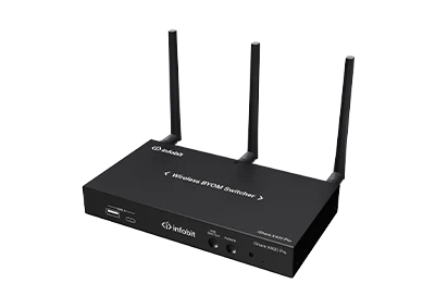
For BYOM spaces, the iShare X400 Pro takes the opposite approach: rather than hardening the cable, it removes it. The room’s USB camera, microphone, and speaker attach to the X400 Pro base, and any participant’s laptop reaches them wirelessly for its own Zoom or Teams call — no cable to the table, no hub tier added to the host, no voltage budget to compute.
The base also serves presentation duty: up to four sources share a single screen, with native AirPlay, Miracast, and Chromecast support alongside Windows/macOS applications and 4K dongles, dual HDMI outputs at up to 4K60, PoE (802.3at) powering, and RSA/AES-encrypted transport for up to 16 simultaneous connections.

TECHNICAL REQUIREMENTS
|
CABLING — ITRANS WP70HBC |
|
|
Cabo |
Cat 6A, single run, terminated T568B both ends |
|
Reach |
40 m / 131 ft @ 4K60 4:4:4 uncompressed · 70 m / 230 ft @ 4K30 |
|
USB transport |
USB 2.0 pass-through, up to 300 Mbps — sized for room cameras, audio endpoints, and HID devices |
|
Plate power |
PoH+ from the receiver — no mains outlet required at the plate |
|
USB-C charging |
Up to 60 W to the presenter’s laptop; requires optional 20 V/6 A adapter at the transmitter |
|
Controlo |
CEC display on/off · RS-232 · API |
|
NETWORK — ISHARE X400 PRO |
|
|
Potência |
PoE (IEEE 802.3at) or local supply |
|
Conectividade |
Wired LAN plus dual-band Wi-Fi; ultrasonic + Bluetooth near-field discovery |
|
Capacity |
Up to 16 simultaneous connections; up to 4 sources on screen |
|
Segurança |
RSA and AES encrypted transport |
|
BYOM compatibility |
Room USB camera, microphone, and speaker exposed wirelessly to participant laptops for Zoom, Teams, and other UC clients |
|
GENERAL |
|
|
Host topology |
Verify total hub tiers from host to farthest endpoint remain within USB specification limits after all displays, bars, and extenders are counted |
|
Compliança |
CE, FCC, RoHS |
APPLICATION DIAGRAM
Reference deployment — medium Microsoft Teams Room. (Diagram placeholder: to be supplied by the design team.)
A representative medium room deploys both products in complementary roles:
- At the table, the iTrans WP70HBC plate accepts the presenter’s USB-C connection — video in, 60 W charging back — with an HDMI + USB-B pair as the second auto-switched input.
- One Cat 6A run leaves the table and carries video, USB, control, and plate power to the receiver at the display location.
- The room camera, touch display, and audio endpoint connect locally at the receiver — every peripheral sits within a short, in-spec USB segment.
- An iShare X400 Pro on the room VLAN provides the wireless path: guests and BYOM users reach the same room peripherals with no physical connection at all.
- Display power state is handled over CEC from the plate; RS-232/API ties both devices into the room control processor.
CONCLUSION
Meeting-room reliability is decided at the physical layer, before any software runs. Rooms engineered with explicit distance, topology, and power budgets — and with long or fragile USB runs moved onto HDBaseT 3.0 or removed via wireless BYOM — exhibit measurably fewer support incidents, faster fault isolation when incidents do occur, and a room design that can be replicated across a building without re-engineering.
The iTrans WP70HBC and iShare X400 Pro address the two ends of that strategy: one makes the necessary cable dependable, the other makes the unnecessary cable disappear.
To review a room design or request a physical-layer audit, contact info@infobitav.com or visit www.infobitav.com.